Post by kcs1 on Mar 28, 2007 8:41:13 GMT -5
Preparing an Athearn BB locomotive for DCC conversion.
This does not cover installing a decoder. Simply how to wire the loco, so that with only a couple of easy splices, it can be converted to DCC with a minimum of trouble. When you finish the technique covered here, your loco will run on DC only in DC mode on DCC. The photos included have information on wiring in a decoder. It is for basic functions only. Other functions you will have to set up yourself.
If you have trouble reading the photos, Email a request to me and I'll Email them to you.
Step 1: Remove shell and any weight covering the motor.
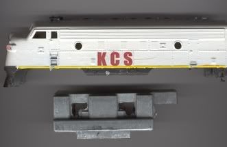
Step 2: Remove contact strip from top of motor. This connects the motor to the trucks.
Step 3:Remove worm gear housing from front truck. Carefully remove worm assembly from truck and set aside. Remove truck.
Repeat step 3 for rear truck. Do not get trucks confused. If you put them back in the wrong place (front truck at rear) your loco
will run backwards.
Step 4: Remove plastic headlight clip and bulb.
Step 5: Grasp motor between thumb and forefinger and push to one side. Pull out motor and one mount pad.
Step 6: Turn motor over and locate the two metal clips on the bottom. They stick downwards and make contact with the
locos frame. These must be removed. Place two strips of electrical tape in the bottom of the motor well of the loco. This will
insure that the motor does not contact the frame. Don't block the holes for the motor pads.

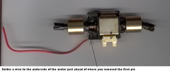
Step 7: Cut a piece of 18 gauge wire long enough to reach from the bottom of the motor to the headlight clip at the front of
the loco. On an F7, this would be 4 1/2 inches. On a PA2, about 6 inches. If in doubt, measure. Solder one end of the wire
to the bottom of the motor, directly in front of the hole left by the first pin.
Step 8: Re-install motor by pushing the side with the mounting pad into place so that it seats firmly in the frame. Using a
small straight-blade screwdriver, gently push the other pad to the side so the motor can be pushed down into it. The motor
must be seated firmly in both pads.
Step 9: Route the wire you soldered to the bottom of the motor around the flywheel. Solder the end of the wire to the very
front of the headlight clip, just above the frame. Twist excess wire into a loop so it is out of the way. You'll need it later when
you install a decoder.
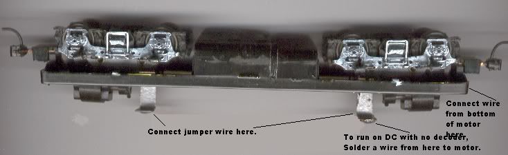
Step 10: Re-install both trucks in the reverse order that you removed them. carefully solder a jumper wire from the top of
the + track pickup on the front truck. Solder the other end of the wire to the top of the + track pickup on the rear truck.
leave enough slack so the trucks can move freely. Do not solder it to the top of the motor!
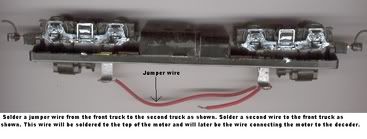
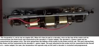
Step 11: Solder a short piece of wire from the top of the motor to the top of + track pickup on the front truck. When you go
to install a decoder, this wire will be removed from the truck and connected to the decoder's + motor output. The decoder
will draw track power from the jumper wire and the wire attached to the frame. This wire will be cut. The part going to the
bottom of the motor will be connected to the decoder's - motor output. The part attached to the frame will be connected to
the decoder's - input. When you re-install the headlight, use the existing clip. Put the bulb in place and bend the contact strip
straight. Cut the strip so that a 1/4 inch sticks out of the clip. Carefully solder a thin wire from the strip to the top of the motor.
Step 12: Install whatever weight was in the loco then install the shell. This may take a bit of doing as the wires do tend to
get in the way of the weight.
When you get a decoder, you'll be ready for the next step. Installing the decoder but, that's
another project.
This does not cover installing a decoder. Simply how to wire the loco, so that with only a couple of easy splices, it can be converted to DCC with a minimum of trouble. When you finish the technique covered here, your loco will run on DC only in DC mode on DCC. The photos included have information on wiring in a decoder. It is for basic functions only. Other functions you will have to set up yourself.
If you have trouble reading the photos, Email a request to me and I'll Email them to you.
Step 1: Remove shell and any weight covering the motor.
Step 2: Remove contact strip from top of motor. This connects the motor to the trucks.
Step 3:Remove worm gear housing from front truck. Carefully remove worm assembly from truck and set aside. Remove truck.
Repeat step 3 for rear truck. Do not get trucks confused. If you put them back in the wrong place (front truck at rear) your loco
will run backwards.
Step 4: Remove plastic headlight clip and bulb.
Step 5: Grasp motor between thumb and forefinger and push to one side. Pull out motor and one mount pad.
Step 6: Turn motor over and locate the two metal clips on the bottom. They stick downwards and make contact with the
locos frame. These must be removed. Place two strips of electrical tape in the bottom of the motor well of the loco. This will
insure that the motor does not contact the frame. Don't block the holes for the motor pads.
Step 7: Cut a piece of 18 gauge wire long enough to reach from the bottom of the motor to the headlight clip at the front of
the loco. On an F7, this would be 4 1/2 inches. On a PA2, about 6 inches. If in doubt, measure. Solder one end of the wire
to the bottom of the motor, directly in front of the hole left by the first pin.
Step 8: Re-install motor by pushing the side with the mounting pad into place so that it seats firmly in the frame. Using a
small straight-blade screwdriver, gently push the other pad to the side so the motor can be pushed down into it. The motor
must be seated firmly in both pads.
Step 9: Route the wire you soldered to the bottom of the motor around the flywheel. Solder the end of the wire to the very
front of the headlight clip, just above the frame. Twist excess wire into a loop so it is out of the way. You'll need it later when
you install a decoder.
Step 10: Re-install both trucks in the reverse order that you removed them. carefully solder a jumper wire from the top of
the + track pickup on the front truck. Solder the other end of the wire to the top of the + track pickup on the rear truck.
leave enough slack so the trucks can move freely. Do not solder it to the top of the motor!
Step 11: Solder a short piece of wire from the top of the motor to the top of + track pickup on the front truck. When you go
to install a decoder, this wire will be removed from the truck and connected to the decoder's + motor output. The decoder
will draw track power from the jumper wire and the wire attached to the frame. This wire will be cut. The part going to the
bottom of the motor will be connected to the decoder's - motor output. The part attached to the frame will be connected to
the decoder's - input. When you re-install the headlight, use the existing clip. Put the bulb in place and bend the contact strip
straight. Cut the strip so that a 1/4 inch sticks out of the clip. Carefully solder a thin wire from the strip to the top of the motor.
Step 12: Install whatever weight was in the loco then install the shell. This may take a bit of doing as the wires do tend to
get in the way of the weight.
When you get a decoder, you'll be ready for the next step. Installing the decoder but, that's
another project.